Wednesday 21 August 2013

How Cell Phone Detector Works

What is Cell Phone Detector?

We are most familiar with cell phone active detectors. The cell phone detectors are mostly hand and pocket-size mobile transmission detectors. It can sense the presence of an activated mobile phone from a distance of one and a half meters. So it can be used to prevent use of mobile phones in examination halls, confidential rooms, etc.
Use of Cell Phone Detector:

It is also useful for detecting the use of mobile phone for spying and un-authorized video transmission. Certain places where the use of mobile phones are not allowed like exam hall, temple, offices and theaters, in those places to detect and restrict the use of mobile phones this proposed system is very helpful. The circuit can detect the incoming and outgoing calls, SMS and video transmission even if the mobile phone is kept in the silent mode.
How Cell Phone Detector Works:
The moment the bug detects RF transmission signal from an activated mobile phone, it starts sounding a beep alarm and the LED blinks. The alarm continues until the signal transmission ceases. An ordinary RF detector using tuned LC circuits is not suitable for detecting signals in the GHz frequency band used in mobile phones.
Frequency Range of Detector:
The transmission frequency of mobile phones ranges from 0.9 to 3 GHz with a wavelength of 3.3 to 10 cm. So a circuit detecting gigahertz signal is required for a mobile bug. The lead length of the capacitor is fixed at 18 mm with a spacing of 8 mm between the leads to get the desired frequency. The disk capacitor along with the leads acts as a small gigahertz loop antenna to collect the RF signals from the mobile phone.
Block Diagram and Working of Cell Phone Detector:

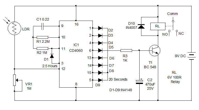
The circuit uses a 0.22μF disk capacitor to capture the RF signals from the mobile phone. Op-amp is used in the circuit is act as a comparator. And transistor in the input to provide very high input impedance; hence the result is in very low input current and very high speed of performance.

The output of the transistor is within 10 MV of either supply voltage terminal. The lead inductance acts as a transmission line that intercepts the signals from the mobile phone.


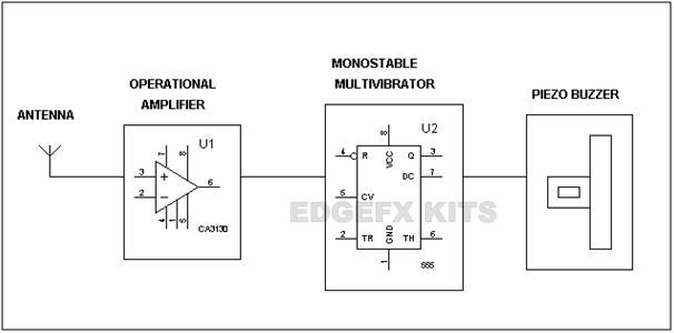
When the mobile phone signal is detected then the output of U1 becomes high and low alternately according to the frequency of the signal. This triggers mono-stable timer U2 through.
And the TR pin of 555timer goes low then pin3 of timer becomes high. When pin3 is high then the buzzer will ring.
You may use a short telescopic type antenna. The unit will give the warning indication if someone uses mobile phone within a radius of 1.5 meters.
Advantages of Cell Phone Detector:
Smaller in size
Detection of hidden cell phones

Monday 19 August 2013

Gas Sensor Application & Features

Gas sensors are a basic component in many security systems and modern methodology, providing key quality control feedback to the system. And these are available in wide specifications depending on the sensitivity levels, type of gas to be sensed, physical measurements and various different elements.

Gas sensors are generally battery operated. They transmit warnings via a series of audible and visible signals such as alarms and flashing lights, when hazardous levels of gas vapors are identified. As detectors measure a gas concentration, the sensor responds to a calibration gas, which serves as the reference point or scale.


The sensor module comprises of a steel exoskeleton under which a sensing component is housed. This sensing component is subjected to current through connecting leads. This current is known as heating current through it; the gases coming close to the sensing component get ionized and are absorbed by the sensing component. This changes the resistance of the sensing component which alters the value of the current going out of it.
FEATURES:
Stable performance, long life, low cost.
Simple drive circuit.
Fast response.
High sensitivity to combustible gas in wide range.
Stable performance, long life, low cost.

Gas detectors can be used to detect burnable, flammable and poisonous gases, and oxygen consumption. This type of device is used widely in industry and can be found in a variety of areas example on oil rigs, to screen produce forms and emerging technologies such as photovoltaic. They might additionally be utilized within firefighting.

The gas sensor is suitable for the detection of combustible gases, for example hydrogen, methane or propane / butane (LPG).


When combustible or reducing gases come in contact with the measuring element, they are subjected to catalytic combustion, which causes a rise in temperature. This rise causes a change in the resistance of the measuring element which is used as a measure of the component of gas being tested. The change in the sensor resistance is obtained as the change of the output voltage across the load resistor (RL) in series with the sensor resistance (RS). When combustible or reducing gases are absorbed by the surface of the sensor, the concentration of the test gas is determined by the change in conductivity. The constant 5V output of the data acquisition board is available for the heater of the sensor (VH) and for the detecting circuit (VC).
A typical working circuit


Sunday 28 July 2013

Relay control using Table clock

image
This circuit can switch on / off a load when the set time arrives. It can be used to switch on AC loads such as TV, Radio, Music system etc. Its triggering pulse is obtained from a small table clock. The switch on / off the time can be set manually through the alarm setting of the clock.
Optocoupler IC MCT2E is used as the link between the clock and the circuit. The alarm buzzer gets around 3 volts when the alarm rings. This voltage is used to trigger the Optocoupler. The Optocoupler has an LED and phototransistor inside. When the LED inside the Optocoupler lights by receiving an external voltage, the phototransistor conducts.
When the Phototransistor conducts, the SCR BT169 fires and latches. This actuates the relay and the load will switch on / off. If the load is connected through the common and NO contacts, the load switches on. If the load is connected through the common and NC contacts, the load switches off when the time arrives.
Relay control using clock
SCR shows latching property when its gate gets a triggering pulse. The SCR continues the conduction even if the gate pulse is removed. It can be switched off only by removing the anode current. So a Push to off switch S1 is used to reset the SCR. Capacitor C1 has a buffering action at the gate of SCR for its smooth working. Diode IN4007 protects the SCR from back emf.
A small low cost table clock can be used for the purpose. Open its back cover and solder two thin wires at the buzzer terminals and connect to the pins 1 and 2 of the Optocoupler observing polarity. Enclose the circuit with the power supply in a case and fix the clock above it using glue. To connect the load, an AC socket can be fixed on the box.

Fridge Timer

premier-fridge-stabilizer-0
Presenting here a circuit for energy saving. It is for your fridge that consumes large quantity of power during peak hours between 6 pm to 9 pm. The condition worsens if there is low voltage in the domestic lines. So the better way to save energy and money is to switch off the fridge during peak hours. This circuit will help you for that. It automatically switches off the fridge around 6 pm and switches it on again after 2.5 hours. So no manual operation is needed and it will do the job regularly.
About IC 4060
IC CD4060 is doing the trick. It is the binary counter cum frequency divider with 10 outputs. Its built in oscillator is based on three inverters. The basic frequency of the oscillator is determined by the values of the capacitor and the resistor connected in its pins 9 and 10 respectively. Pin 11 is the Osc in to which the pulses from this external oscillator enter. Each output of IC turns high in the negative transition after completing one timing cycle. To get maximum time delay, output Q11 is omitted so that double time delay is available between the outputs Q10 and Q12.
Inside the IC, there is an oscillator and 14 series connected Bistables (Ripple cascade arrangement). Internally the oscillator signal is applied to the first bistable which drives the second bistable and so on. Since each bistable divides its input signal by two, a total of fifteen signals are available, each of half the frequency of the previous one. Ten of these fifteen signals are available on the output pins Q4- Q14.
Timing cycle calculation
Time t = 2 n / f osc = Seconds
n is the selected Q output number
f osc = 1 / 2.5 (R1XC1) = in Hertz
R1 is the resistance at Pin 10 in Ohms and C1, the capacitor at Pin 9 in Farads.
For example if R1 is 1M and C1 0.22 the basic frequency f osc is
1 / 2.5(1,000,000 x 0.000,000 22) = 1.8 Hz
FRIDGE-TIMER
Circuit working
An LDR is used as the light sensor to detect the darkness around 6 pm. During day light, LDR has less resistance and it conducts. This keeps the reset pin 12 of IC1 high and the IC remains off without oscillating. VR1 adjust the resetting of IC at the particular light level in the room, say around 6 pm. When the light level in the room drops below the preset level, IC1 starts oscillating. After 20 seconds, its pin 5 turns high and triggers the relay driver transistor T1. Normally the power supply to the fridge is provided through the Comm and NC contacts of the relay. So when the relay triggers, the contacts break and the power to the fridge will be cut off.
The other outputs of the IC1 turns high one by one as the binary counter advances. But since the outputs are taken to the base of T1 through the diodes D2 through D9, T1 remains on during the entire period until the output pin 3 turns high after 2.5 hours. When the output pin 3 turns high, diode D1 forward biases and inhibits the oscillation of IC. At this time, all the outputs except pin 3 turns low and T1 switches off. Relay deenergizes and the Fridge again gets power through the NC contact. This condition remains as such till the LDR gets light again in the morning.IC1 then resets and pin3 again turns low. So during day time also, the Fridge works as usual. Only during the peak hours say between 6 pm and 8.30 pm, the Fridge remains off. By increasing the value of either C1 or R1, you can increase the time delay to 3 or 4 hours.
How to set?
Assemble the circuit on a common PCB and enclose in a Box. You can use the case of a stabilizer so that the output plug can be fixed easily. Use a 9 volt 500 mA transformer power supply for the circuit. Take the phase line from the Transformer primary and connect it to the Common contact of the relay. Connect another wire to the NC contact of the relay and connect its other end to the Live pin of the socket. Take a wire from the Neutral of the transformer primary and connect it to the Neutral pin of the Socket. So now the socket can be used to plug in the Fridge. Fix the LDR outside the box where day light is available (note that the room light during night should not fall on the LDR). If the room light is not sufficient during day time, keep the LDR outside the room and connect it to the circuit using thin wires. Adjust the preset VR1 to set the sensitivity of LDR at the particular light level.

Over Voltage Protector

Here is a simple over voltage protector circuit that breaks the power to the load if the voltage increases above the preset level. The power will be restored only if the voltage drops to normal level. This kind of circuit is used in voltage stabilizers as over load protection.
The circuit uses a Zener controlled relay driver to cut off the power in the over voltage condition. A 0-9 volt transformer, diode D1 and the smoothing capacitor provides 9 volts DC for the circuit. Any voltage increase in the Primary of the transformer (as the mains voltage increases) will reflect as a corresponding voltage increase in its secondary also. This principle is used in the circuit to trigger the relay. When the input voltage to the primary of the transformer (around 230 volts), Zener will be out of conduction (as set by VR1) and the relay will be in the de- energized condition. The Load will get power through the common and the NC contacts of the Relay. In this state, LED will be off.
When the voltage increases, Zener diode conducts and the relay will be activated. This breaks the power supply to the load. LED shows the activation status of the relay. Capacitor C1 acts as a buffer at the base of T1 for the smooth working of T1 to prevent relay clicking during its activation/deactivation.
Over-Voltage-Protector
Load is connected through the Common and the NC (Normally Connected) contacts of the relay as shown in the diagram. The phase line is connected through the relay contacts. Neutral should go directly to the load.
Before connecting the load, slowly adjust VR1 till LED just turns off assuming that the lines voltage is between 220-230 volts. If necessary, check the line voltage using an AC volt meter. The circuit is ready for use. Now connect the load. When the voltage increases, Zener will conduct and actuates the relay. When the lines voltage returns to normal, again the load will get power

Simple DC-DC Converter


Presenting here a simple DC-DC converter circuit to power various DC operated circuits. It can provide DC power supply up to 18 volts DC. You can simply select the output voltage by changing the value of the Zener diode ZD. The circuit has both voltage and current regulation.
imagesInput voltage for the circuit is obtained from a 18 volt 500 mA transformer based power supply . You can also use input voltage from a battery.The 18 volts DC from the power supply is given to the collector and base of the Medium power transistor BD139 (T1). Resistor R1 limits the base current of T1 so that the output voltage will be current regulated.
DC-DC-Converter-circuit
Zener diode ZD regulates the output voltage. Select  the appropriate value of Zener to fix the output voltage. For example, if the Zener diode is a 12 volt one, the circuit gives 12 volts DC at the output. Diode D1 is used as a polarity protector.LED provides power on status.

Portable Emergency Light cum Mobile Charger

Portable Emergency Light cum Mobile ChargerHere is Portable Emergency Lamp cum Mobile charger. It uses a high bright White LED that can give sufficient light in the room when the mains power fails. It can be also used as a Mobile charger in the plug in mode as well during journey.
Power supply for the circuit is derived from a 0-6 volt 300 mA step-down transformer , a fullwave rectifier comprising D1 through D4 and the smoothing capacitor C1. The Emergency light circuit consists of diode D5, resistor R2 and the Transistor T1.When the mains power is available, diode D5 forward biases and the 6 volt battery charges through resistor R2.At the same time, the PNP transistor T1 will be out of conduction since its base is kept high through R1. The white LED connected to the collector of T1 remains off. When the mains power fails, D5 reverse biases and the base of T1 gets a negative bias and it conducts. White LED then turns on using the power from the battery.
The Mobile charger section of the circuit consists of a Zener based regulated power supply. Charging current can be tapped from the points A and B using suitable connector.
Emergency-light-cum-Mobile-
Assemble the circuit on a common PCB and enclose in a plug in type adapter box so that it can be plugged directly into the wall socket. Use a small 6 volt rechargeable battery to make the unit compact. Use a high bright White LED to get sufficient light

Secure Communication Using 3-Pin RF Module

About RF Module:
In generally, the wireless systems designer has two overriding constraints: it must operate over a certain distance and transfer a certain amount of information within a data rate. The RF modules are very small in dimension and have a wide operating voltage range i,e 3V to 12V.
Basically the RF modules are 433 MHz RF transmitter and receiver modules. The transmitter draws no power when transmitting logic zero while fully suppressing the carrier frequency thus consume significantly low power in battery operation. When logic one is sent carrier is fully on to about 4.5mA with a 3volts power supply. The data is sent serially from the transmitter which is received by the tuned receiver. Transmitter and the receiver are duly interfaced to two microcontrollers for data transfer.
secure
Features:
  • Receiver frequency 433MHz
  • Receiver typical frequency 105Dbm
  • Receiver supply current 3.5mA
  • Low power consumption
  • Receiver operating voltage 5v
  • Transmitter frequency range 433.92MHz
  • Transmitter supply voltage 3v~6v
  • Transmitter output power 4v~12v
How 3-pin RF Module Works in sending the secrete information:
We can connect the 3-pin RF modules directly to the controller; there is need of any encoder and decoder. The working of 3-pin RF transmitter and receiver modules is as follows in sending/transforming the secrete information. Let’s see how they work.
Working RF Transmitter Module:
From the circuit, the power supply +5V is connected to the 40 pin of microcontroller and ground is connected to 20th pin. Here, we got two switches which are duly connected to microcontroller with pulled up to 5V and this two switches form the input command to the microcontroller. We also got an LCD display for displaying the data to be transmitted. We also have an arrangement for a computer key board to be connected for positive and negative part from clock and data pin which is connected as input to the microcontroller from the output of key board and that data is ultimately displayed in the LCD. We also have one RF transmitter. It has VCC supply, GND. Data pin which goes to microcontroller. The program is so written that by appropriate operation of this working we first make the key board active. Once the key board is made active by pressing the buttons then the keyboard entry can take place which is displays in LCD. If it has to be sent against codes varying from 0 to 9 this will be displayed in LCD. Here every press is advancing as per the code from 0 to 9 and ultimately when we press one of the push button for sending it will go to microcontroller and then to the RF transmitter module over a 433 MHz frequency transmitted from antenna.
secure communi
Working of RF Receiver Module:
At receiver end we have similar connections for power supply as microcontroller needs +5V. Similarly to transmitter, hear also we are using two push buttons with 10k pull up resistors through 5V supply for RF Module. We are using pin 3.0 to connect data pin of RF module and  1 and 2 pins of RF module is used for GND and VCC.
We also have two buttons for selection of code and for receiving the data. Once the data is received by the receiver module that data is demodulated and goes to the receiver pin 10 of microcontroller as per the program. It then display the message on LCD display.
secure communi circuit

Musical Door Bell

Here is a Mini project for students. This is a simple battery operated Music bell circuit that generates a sweet melody for one minute when it is triggered. It uses the ROM IC UM66 to produce the melody. The music stops automatically.

A push switch is used to trigger the circuit. When the push switch is pressed momentarily, NPN transistor T1 conducts and pull the base of T2 and it also conducts. When T2 conducts, C1 charges and provides power to IC UM66. Zener diode ZD is used to regulate the supply voltage to UM66 to 3 volts. When UM 66 gets 3 volts supply, it oscillates and the music tone from it will be amplified by T3 which can be heard through the speaker. Use a small 2 inch speaker.
Musical-Bell-Circuit
um66-pin-configurationsBC557

Saturday 27 July 2013


We all know that breathing an oxygen rich liquid is an old idea which does have some advantages but it has more detriments than benefits. For example the removal of carbon dioxide from bloodstream becomes a big problem, which ultimately leads to many other problems. So the Researchers at Boston Children’s Hospital came up with a new idea! They created micro-particles that can be injected into your bloodstream and oxygenate it. These particles are pockets of oxygen in layers of lipids, i.e. specifically fats. This is then suspended in liquid, which can be injected into the bloodstream. Now this becomes quite handy because you don’t have to breathe at all till the time these particles carry oxygen.

This Injectable oxygen can keep people alive for 20 to 30 minutes without inhaling any oxygen. The implications of this type of oxygen are enormous. Think about a patient who is unable to breathe, with the help of this oxygen doctors can keep him alive for a few minutes and can potentially save his life as well. We don’t know whether it will be fine to use this oxygen to breathe underwater, but if the answer is “YES” then there are a lot of new dimensions to explore!