


Secure Communication Using 3-Pin RF Module
About RF Module:
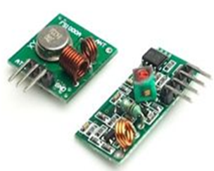
In generally, the wireless systems designer has two overriding constraints: it must operate over a certain distance and transfer a certain amount of information within a data rate. The RF modules are very small in dimension and have a wide operating voltage range i,e 3V to 12V.
Basically the RF modules are 433 MHz RF transmitter and receiver modules. The transmitter draws no power when transmitting logic zero while fully suppressing the carrier frequency thus consume significantly low power in battery operation. When logic one is sent carrier is fully on to about 4.5mA with a 3volts power supply. The data is sent serially from the transmitter which is received by the tuned receiver. Transmitter and the receiver are duly interfaced to two microcontrollers for data transfer.
Features:
- Receiver frequency 433MHz
- Receiver typical frequency 105Dbm
- Receiver supply current 3.5mA
- Low power consumption
- Receiver operating voltage 5v
- Transmitter frequency range 433.92MHz
- Transmitter supply voltage 3v~6v
- Transmitter output power 4v~12v
How 3-pin RF Module Works in sending the secrete information:
We can connect the 3-pin RF modules directly to the controller; there is need of any encoder and decoder. The working of 3-pin RF transmitter and receiver modules is as follows in sending/transforming the secrete information. Let’s see how they work.
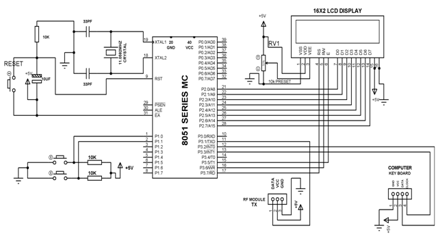
Working RF Transmitter Module:
From the circuit, the power supply +5V is connected to the 40 pin of microcontroller and ground is connected to 20th pin. Here, we got two switches which are duly connected to microcontroller with pulled up to 5V and this two switches form the input command to the microcontroller. We also got an LCD display for displaying the data to be transmitted. We also have an arrangement for a computer key board to be connected for positive and negative part from clock and data pin which is connected as input to the microcontroller from the output of key board and that data is ultimately displayed in the LCD. We also have one RF transmitter. It has VCC supply, GND. Data pin which goes to microcontroller. The program is so written that by appropriate operation of this working we first make the key board active. Once the key board is made active by pressing the buttons then the keyboard entry can take place which is displays in LCD. If it has to be sent against codes varying from 0 to 9 this will be displayed in LCD. Here every press is advancing as per the code from 0 to 9 and ultimately when we press one of the push button for sending it will go to microcontroller and then to the RF transmitter module over a 433 MHz frequency transmitted from antenna.
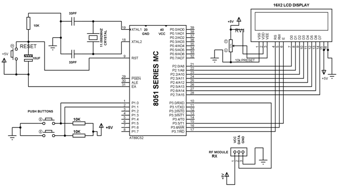
Working of RF Receiver Module:
At receiver end we have similar connections for power supply as microcontroller needs +5V. Similarly to transmitter, hear also we are using two push buttons with 10k pull up resistors through 5V supply for RF Module. We are using pin 3.0 to connect data pin of RF module and 1 and 2 pins of RF module is used for GND and VCC.
We also have two buttons for selection of code and for receiving the data. Once the data is received by the receiver module that data is demodulated and goes to the receiver pin 10 of microcontroller as per the program. It then display the message on LCD display.
Categories: DIY PROJECTS
0 comments:
Post a Comment