


Presenting here a circuit for energy saving. It is for your fridge that consumes large quantity of power during peak hours between 6 pm to 9 pm. The condition worsens if there is low voltage in the domestic lines. So the better way to save energy and money is to switch off the fridge during peak hours. This circuit will help you for that. It automatically switches off the fridge around 6 pm and switches it on again after 2.5 hours. So no manual operation is needed and it will do the job regularly.
About IC 4060
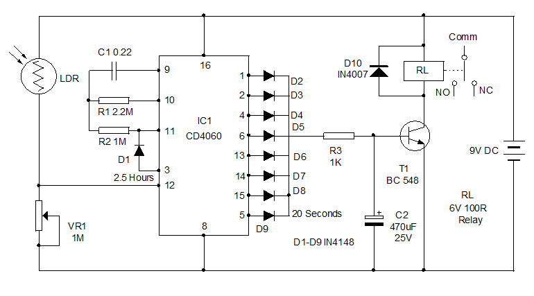
IC CD4060 is doing the trick. It is the binary counter cum frequency divider with 10 outputs. Its built in oscillator is based on three inverters. The basic frequency of the oscillator is determined by the values of the capacitor and the resistor connected in its pins 9 and 10 respectively. Pin 11 is the Osc in to which the pulses from this external oscillator enter. Each output of IC turns high in the negative transition after completing one timing cycle. To get maximum time delay, output Q11 is omitted so that double time delay is available between the outputs Q10 and Q12.
Inside the IC, there is an oscillator and 14 series connected Bistables (Ripple cascade arrangement). Internally the oscillator signal is applied to the first bistable which drives the second bistable and so on. Since each bistable divides its input signal by two, a total of fifteen signals are available, each of half the frequency of the previous one. Ten of these fifteen signals are available on the output pins Q4- Q14.
Timing cycle calculation
Time t = 2 n / f osc = Seconds
n is the selected Q output number
f osc = 1 / 2.5 (R1XC1) = in Hertz
R1 is the resistance at Pin 10 in Ohms and C1, the capacitor at Pin 9 in Farads.
For example if R1 is 1M and C1 0.22 the basic frequency f osc is
1 / 2.5(1,000,000 x 0.000,000 22) = 1.8 Hz
n is the selected Q output number
f osc = 1 / 2.5 (R1XC1) = in Hertz
R1 is the resistance at Pin 10 in Ohms and C1, the capacitor at Pin 9 in Farads.
For example if R1 is 1M and C1 0.22 the basic frequency f osc is
1 / 2.5(1,000,000 x 0.000,000 22) = 1.8 Hz
Circuit working
An LDR is used as the light sensor to detect the darkness around 6 pm. During day light, LDR has less resistance and it conducts. This keeps the reset pin 12 of IC1 high and the IC remains off without oscillating. VR1 adjust the resetting of IC at the particular light level in the room, say around 6 pm. When the light level in the room drops below the preset level, IC1 starts oscillating. After 20 seconds, its pin 5 turns high and triggers the relay driver transistor T1. Normally the power supply to the fridge is provided through the Comm and NC contacts of the relay. So when the relay triggers, the contacts break and the power to the fridge will be cut off.
The other outputs of the IC1 turns high one by one as the binary counter advances. But since the outputs are taken to the base of T1 through the diodes D2 through D9, T1 remains on during the entire period until the output pin 3 turns high after 2.5 hours. When the output pin 3 turns high, diode D1 forward biases and inhibits the oscillation of IC. At this time, all the outputs except pin 3 turns low and T1 switches off. Relay deenergizes and the Fridge again gets power through the NC contact. This condition remains as such till the LDR gets light again in the morning.IC1 then resets and pin3 again turns low. So during day time also, the Fridge works as usual. Only during the peak hours say between 6 pm and 8.30 pm, the Fridge remains off. By increasing the value of either C1 or R1, you can increase the time delay to 3 or 4 hours.
How to set?
Assemble the circuit on a common PCB and enclose in a Box. You can use the case of a stabilizer so that the output plug can be fixed easily. Use a 9 volt 500 mA transformer power supply for the circuit. Take the phase line from the Transformer primary and connect it to the Common contact of the relay. Connect another wire to the NC contact of the relay and connect its other end to the Live pin of the socket. Take a wire from the Neutral of the transformer primary and connect it to the Neutral pin of the Socket. So now the socket can be used to plug in the Fridge. Fix the LDR outside the box where day light is available (note that the room light during night should not fall on the LDR). If the room light is not sufficient during day time, keep the LDR outside the room and connect it to the circuit using thin wires. Adjust the preset VR1 to set the sensitivity of LDR at the particular light level.
0 comments:
Post a Comment